Sections:
- Team Orion
- Inspiration
- Featrues
- Recommendations
0 Team Orion #
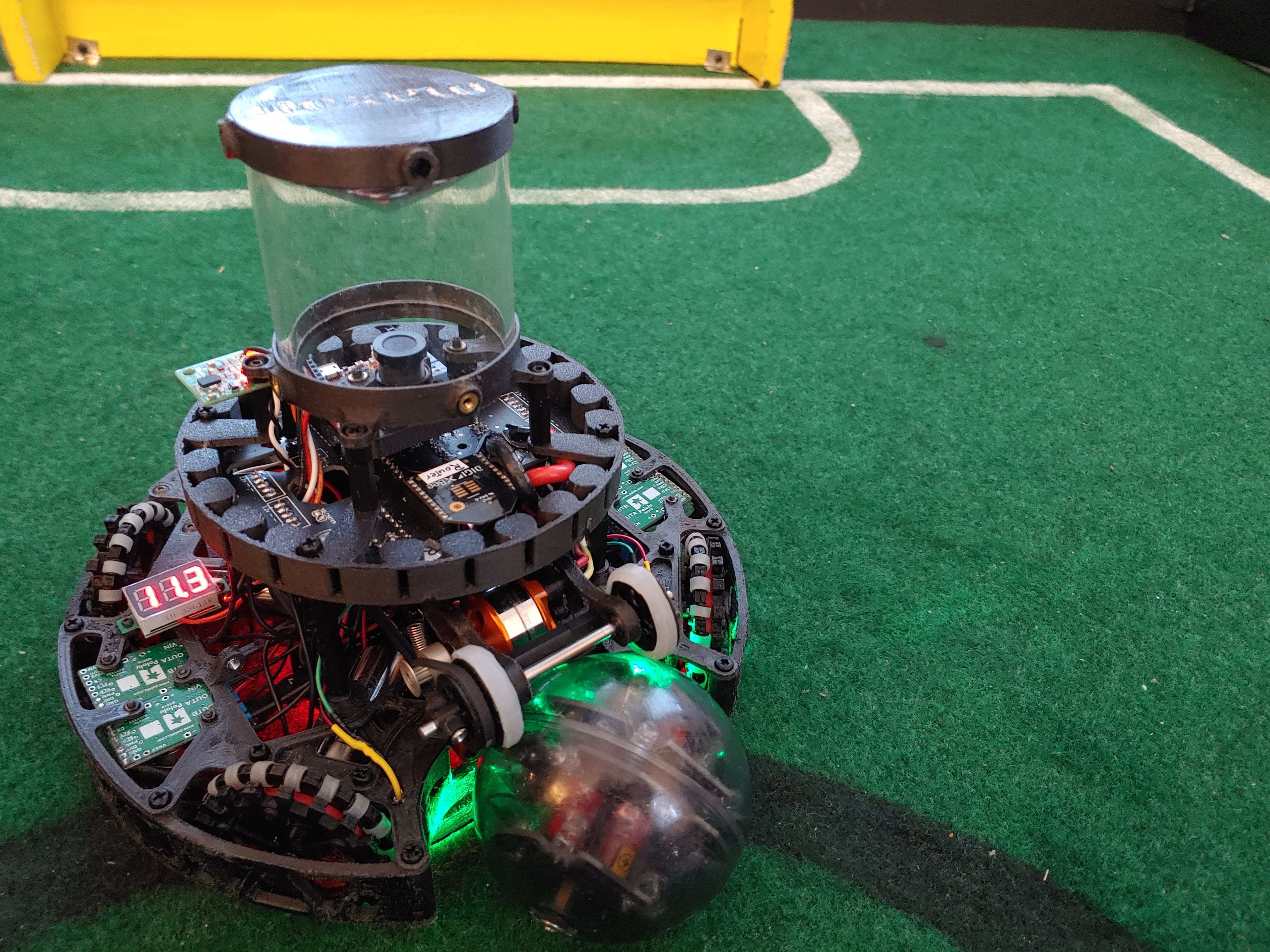
In high school I founded Team Orion with 4 of my friends to build autonomous soccer robots. We were National champions in 2019, 2021, and 2022. We participated in the Lightweight League in 2019 and 2021, and the Open League in 2022. In the international 2021 competition we represented the United States at the virtual RoboCup2021 Worldwide competition and won the best video award.
We had no mentors. I was in charge of the electrical engineering including PCB design/assembly/testing, Keiji Imai mechanical engineering, Niklas Austermann computer vision, and Danil Korennykh software. Although we had roles, we each contributed outside our areas. For example, I was also involved in the software development and strategy.
Keiji has an amazing post about the mechanical engineering involved.
1 Inspirations (go to section 2 if you want details of our robot) #
The following is a list of ideas from teams at the 2019 world cup that we implimented thein 2021. We were the first team to fit all of the following features into our robot under the weight limit (1100g).
I explain the features in the next section #
M&A (australia) - 1st place #
strengths: #
speed and reliability
features Orion used from the team: #
- circular line detection PCB and koig algorithm
- Maxon DCX19 overvolting
- role switching
- Orbit function
- vision based goalie and striker
- Thermoformed mirror (360 vision)
SkyCrew (JAPAN) - 2nd place #
strengths: #
reliability of hardware and software
features Orion used from the team: #
- circular line detection PCB and koig algorithm
- role switching
- vision based goalie and striker
- Thermoformed mirror (360 vision)
- kicker
LEGEND (JAPAN) - 3rd place #
strengths: #
Speed and kicker
features Orion used from the team: #
- role switching (although their goalie was mostly broken)
- vision based goalie and striker
- Thermoformed mirror (360 vision)
- Dribbler
- Kicker
- Angled motors
2 Features of Orions Robots #
Main PCB #
The main PCB has 24 Infrared sensors (TSSP4038) to detect the ball. Each has a lowpass filter to convert the digitl pulses to an analog signal for ease of processing. These signals are passed into Analog to Digital Converters to reduce the amount of pins used on the main processor.
The main processor is a Teensy 4.1, with wireless communiction through XBee connected through UART. The XBee allows wireless debugging when one is connected to the computer and another to a robot. During matches, both XBees are in the robots to switch roles of goalie vs striker. We found the simple algorithm of the robot closer to the ball being striker to work well.
The main PCB also has connections for the battery, a lightgate, communication to motor drivers (through PWM) and 10 pin IDC cable to the line PCB for power + line sensor values.
A lightgate is an LED, usually green in RoboCup, shining towards a photoresistor in the ball capture zone. When a ball is in the ball capture zone, the LED is obstructed and so the photoresistor can sense it.
The OpenMV camera is in the exact center to make vision symmetrical and easier mathmatically. It slides in from the top pointing upwards into a conical mirror for 360 vision.
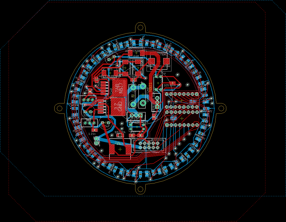
Line PCB #
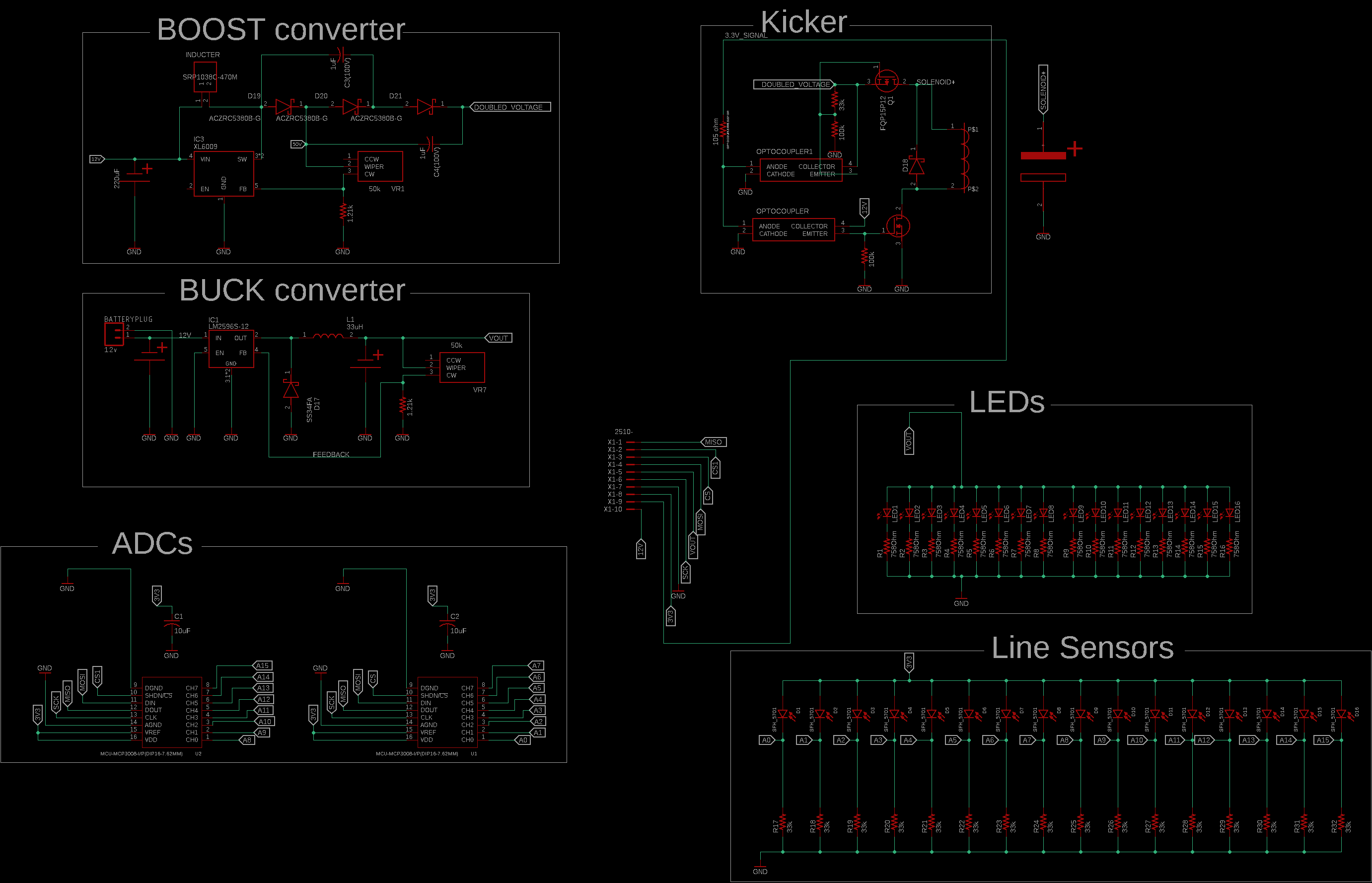
The Line PCB has:
- 12V -> 5V buck converter
- 12V -> 120V Boost + voltage doubler circuit
- 120V solenoid (kicker) trigger circuit
- Huge capacitor
- Line sensors
- ADCs (MCP3008)
My Maker portfolio describes the boost and trigger circuit concisely:
The buck converter is exactly like a COTS buck converter. Implimenting it just saved space, weight, and helped me learn. The voltage booster uses an XL6009 IC to converter 12V to 60V, then a voltage doubler circuit using diodes and the original switching of the XL6009 to reach 120V.
The trigger circuit uses optocouplers to insulate the logic from the high voltage. It also uses P and N channel mosfets to make sure the capacitor and solenoid are isolted from the robot when firing.
Dribbler #
We used a drone motor and esc to spin a custom made silicone roller that makes the ball spin towards the robot. For details, read Keiji’s post
Thermoformed mirror (360 vision) #
Niklas was mainly in charge of the mirrors and vision system. He heated up a vinyl mirror and pressed it onto a wooden or plastic mold. When the mirror cooled down, it would be in the desired conical shape. Positioning the camera pointing upwards into the mirror allows 360 degree vision with only 1 camera.
software strategy #
orbit #
The Orbit function is a function that takes in the angle of the ball measured from the front of the robot and outputs the angle the robot should add to it to get behind it. Ex: ball is at 45 -> output is 60 -> 45 + 60 = 105 so the robot should go towards 105 degrees.
typically it looks like y = min(90, 0.04e^(0.12ballangle))
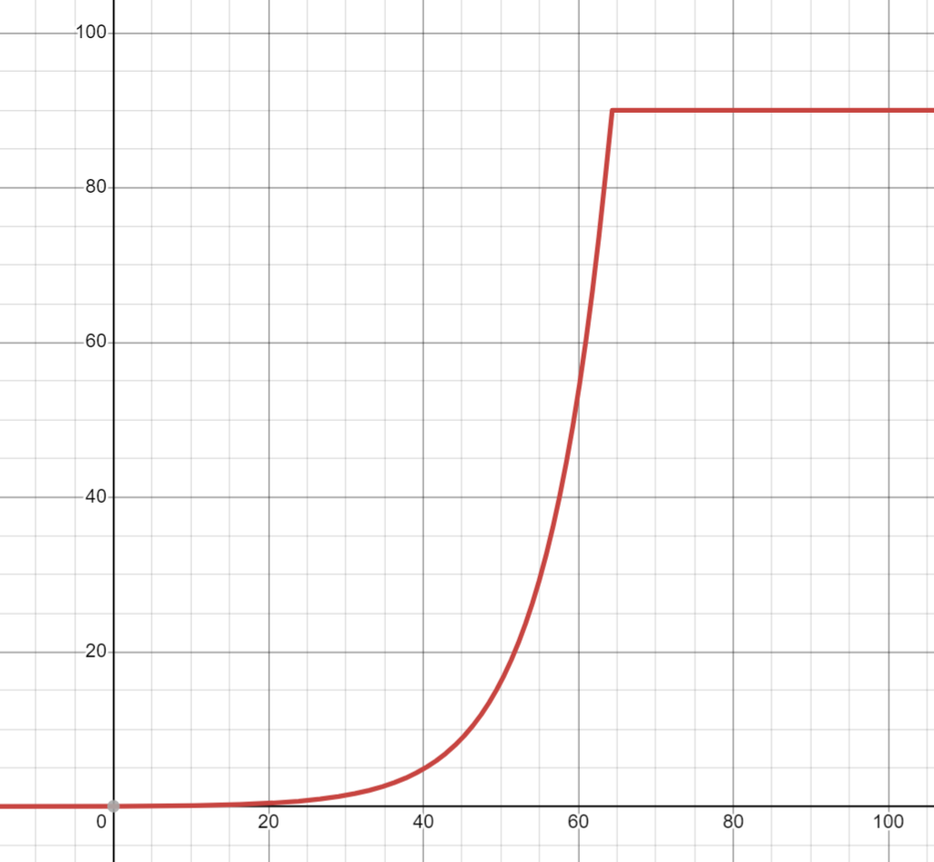
This makes the robot motion smooth compared to a mountin of if-statements.
With just an orbit function, the robots orbit is exaggerted when the ball is far, so a dampen function (input: distance to ball output: scaling factor from 0 to 1) is multiplied to the orbit function to scale down the offset as distance increases.
motor angle #
To make the ball capture sone wider, we have a 40 degree motor angle from the horizontal instead of n equally spaced 45. We use vectors to compute where to go, so to convert from vectors to motor speeds, we take the magnitude of the perpendiculr component of the vector with respect to a motor. we calcualted each motor power by doing: sin(desired movement angle - motor angle)
So if the desired movement is the same as the motor, the motor power is 0.
To scale up the motor powers to utilize full power, we devide the final ratios by the biggest ratio. This is needed because going forward would result in a ratio of about 1/root(2) for all motors, but we want 1 (full 100%).
line algorithm (Koig) #
For our line algorithm we took inspiration from skycrew and came up with our own algorithm called Koig. The line sensors are positioned in a continuous ring. So we sum up the vectors of the furthest two line sensors that are triggered. This is called the line vector and it points towards the line. when this line vecotr flips 180 degrees, we passed over the line.
Projection: When we detect the line and the desired move angle is towards the line, we project the move angle to perpendicular to the line angle. In other words, we move along the line. This produces a nice scooping pattern when the ball is on the line.
overvolting #
We used Maxon DCX19 motors and overvolted then with 12V for speed. This is by far the fastest, most popwerful, and efficiant motor setup in RoboCupJunior so far.
See our 2021 Technical paper for more.
Recommendations for students interested in RoboCup Junior: #
- Go to a meet and join Princeton Soccer Robots (This is by FAR the most useful and helpful advice)
- RoboCupJunior Discord server
- RCJ SSL server (this is for the college league so be more thoughtful with your questions here)
- Great scott youtube (Great for getting into electronics)
- Digikey Kicad tutorial for learning KiCAD